
|
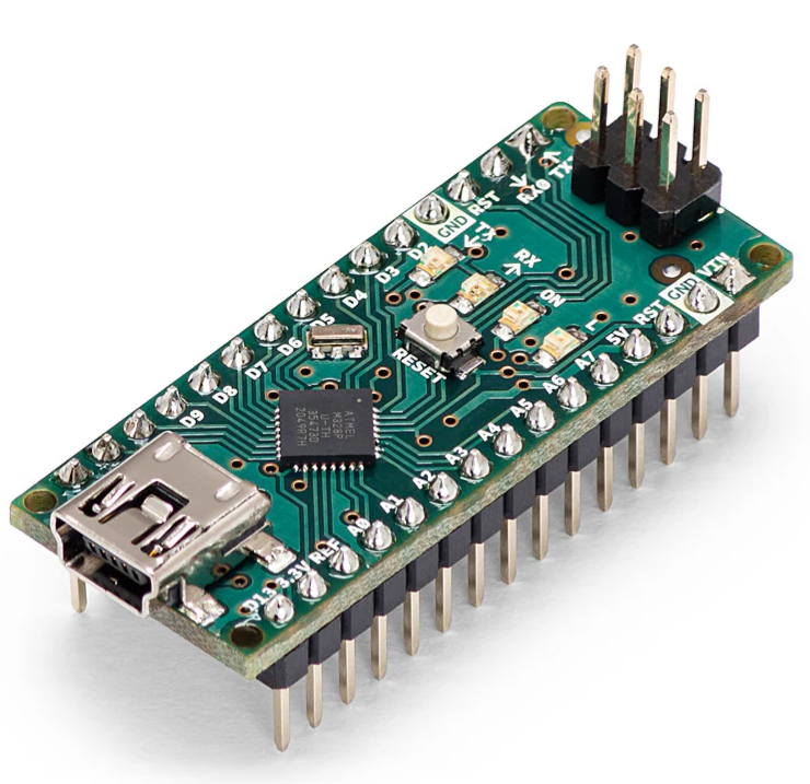
Arduino nanoArduino
|
|

|
arduino IDEArduino
|
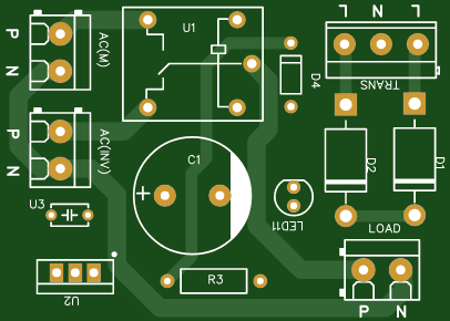
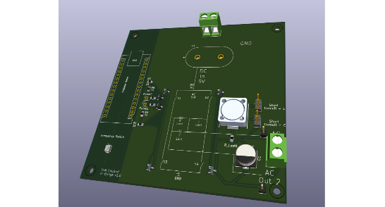
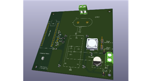
Simple H-Bridge
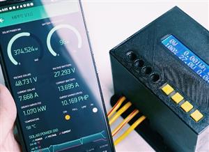
🔋 Arduino Nano 50 Hz SPWM H-Bridge Driver
This project uses an Arduino Nano to generate 50 Hz sinusoidal PWM (SPWM) signals for driving a simple H-bridge inverter. It produces two complementary PWM outputs on pins D5 and D6, suitable for MOSFET or IGBT gate drivers (e.g. IR2104, IR2110).
A push-button on D3 toggles the PWM carrier frequency between ≈977 Hz and ≈244 Hz, allowing quick testing of different switching speeds. The sine waveform is created from a 128-point lookup table, updated by a Timer2 interrupt, while Timer0 handles high-speed PWM generation.
✨ Features
50 Hz sinusoidal PWM output
Complementary outputs (D5 & D6) for H-bridge control
Switch-selectable carrier frequency (977 Hz / 244 Hz)
Hardware-based timing for stable, low-jitter waveform
Compatible with standard Arduino Nano boards
⚙️ Technical Info
ParameterValuePWM PinsD5 (OC0B) & D6 (OC0A)Control InputD3 (toggle switch, pull-up enabled)Sine Frequency50 Hz (fixed)Table Size128 samplesSupply Voltage5 V (Arduino logic)
🔌 Applications
Small inverter or UPS prototypes
SPWM learning and testing
AC waveform or motor control experiments
Simple, reliable, and educational — this project demonstrates how to generate clean sinusoidal PWM using the Arduino’s built-in timers for real H-bridge control.
/*
  Arduino Nano - 50 Hz Sinusoidal PWM (SPWM) on D5 & D6
  This code generates two complementary PWM signals with dead time.
  A switch on D3 toggles the carrier frequency between two states.

  - Carrier PWM Frequencies (Fast PWM Mode):
    - State 1: ~977 Hz (Prescaler 64)
    - State 2: ~244 Hz (Prescaler 256)
  - Sine Wave Frequency: ~50.08 Hz (constant)
  - Output: Complementary SPWM on D5 & D6.
*/

#include <Arduino.h>

// Define the pin for the toggle switch.
#define SWITCH_PIN 3

// A larger table size gives a smoother sine wave.
#define SINE_TABLE_SIZE 128
// Defines the dead time. Not needed because of the natural deadtime with R3 and R1
#define DEAD_TIME 0

// Array to store pre-calculated sine wave duty cycle values.
byte sine_table[SINE_TABLE_SIZE];

// Volatile variable for the current position in the sine table.
volatile int table_index = 0;

// --- MODIFICATION: State variables for the toggle logic ---
// Tracks whether we are in high or low frequency mode.
volatile bool useHighFrequency = true;
// Stores the last-read state of the button to detect a press.
int lastButtonState = HIGH;

void setup() {
  // --- Step 1: Pre-calculate the sine lookup table ---
  for (int i = 0; i < SINE_TABLE_SIZE; i++) {
    // Calculate a sine wave value, scale it from -1..1 to 0..255
    float val = sin(i * 2.0 * PI / SINE_TABLE_SIZE);
    sine_table[i] = (byte)((val + 1.0) * 127.5);
  }

  // --- Step 2: Configure the switch pin ---
  // Set D3 as an input with an internal pull-up resistor.
  pinMode(SWITCH_PIN, INPUT_PULLUP);
  // Read the initial state of the button.
  lastButtonState = digitalRead(SWITCH_PIN);

  // --- Step 3: Configure Timer0 for complementary PWM carrier ---
  pinMode(6, OUTPUT); // D6 = OC0A
  pinMode(5, OUTPUT); // D5 = OC0B

  TCCR0A = 0; // Clear control registers
  TCCR0B = 0;

  // --- MODIFICATION: Set Fast PWM mode for more frequency options ---
  // Mode 3: Fast PWM, TOP = 0xFF (255)
  TCCR0A |= (1 << WGM01) | (1 << WGM00);

  // Configure complementary (inverted) outputs on OC0A and OC0B.
  TCCR0A |= (1 << COM0A1) | (1 << COM0B1) | (1 << COM0B0);

  // --- MODIFICATION: Set initial prescaler for ~977 Hz ---
  // Freq = 16,000,000 / (64 * 256) = 976.56 Hz
  TCCR0B |= (1 << CS01) | (1 << CS00); // Prescaler 64

  // --- Step 4: Configure Timer2 to generate the 50 Hz update interrupt ---
  // This part is unchanged.
  TCCR2A = 0; // Clear control registers
  TCCR2B = 0;

  TCCR2A |= (1 << WGM21); // Set CTC Mode
  TCCR2B |= (1 << CS22);  // Set prescaler to 64

  // OCR2A = (16,000,000 / (64 * 50Hz * 128 steps)) - 1 = 38
  OCR2A = 38;

  // Enable Timer2 Compare Match A Interrupt.
  TIMSK2 |= (1 << OCIE2A);

  // Enable global interrupts.
  sei();
}

// ISR: This function is automatically called by the Timer2 hardware interrupt.
// It continues to update the sine wave duty cycle regardless of the carrier frequency.
ISR(TIMER2_COMPA_vect) {
  byte duty_cycle = sine_table[table_index];

  // Apply dead time.
  OCR0A = duty_cycle - DEAD_TIME;
  OCR0B = duty_cycle + DEAD_TIME;

  table_index++;
  if (table_index >= SINE_TABLE_SIZE) {
    table_index = 0;
  }
}

// --- MODIFICATION: The main loop now implements the toggle logic ---
void loop() {
  // Read the current state of the switch.
  int currentButtonState = digitalRead(SWITCH_PIN);

  // Check if the button was just pressed (transition from HIGH to LOW).
  if (currentButtonState == LOW && lastButtonState == HIGH) {
    // --- ACTION: BUTTON WAS PRESSED ---

    // Toggle the frequency state.
    useHighFrequency = !useHighFrequency;

    // Clear the prescaler bits on Timer0 before setting new ones.
    TCCR0B &= ~((1 << CS02) | (1 << CS01) | (1 << CS00));

    if (useHighFrequency) {
      // Set prescaler to 64 for ~977 Hz carrier frequency.
      TCCR0B |= (1 << CS01) | (1 << CS00);
    } else {
      // Set prescaler to 256 for ~244 Hz carrier frequency.
      // Freq = 16,000,000 / (256 * 256) = 244.14 Hz
      TCCR0B |= (1 << CS02);
    }

    // Add a small delay for switch debouncing.
    // This prevents a single physical press from being registered multiple times.
    delay(50);
  }

  // Update the last button state for the next loop iteration.
  lastButtonState = currentButtonState;
}
Simple H-Bridge
*PCBWay community is a sharing platform. We are not responsible for any design issues and parameter issues (board thickness, surface finish, etc.) you choose.


- Comments(0)
- Likes(0)
 More by Engineer
-
-
-
-
-
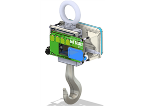
BLASTIC IoT SCALE - a Precious Plastic Open Source Fund's project
345 0 1 -
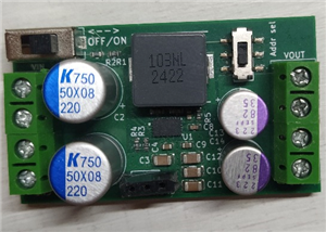
I2C controllable buck-boost converter (2Layer version)
387 0 0 -
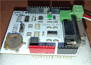
Shield Modbus RTU para Arduino R3 y R4 RS232 RS485
230 0 0 -