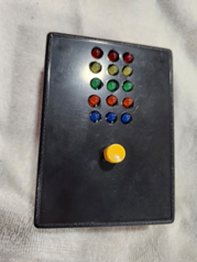
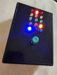
Summary: My project is a slot machine using 15 colored LEDs to form three reels. A single button starts the reels, resets the game with each press, and powers the device. The machine turns off automatically after about eight minutes of inactivity. This describes placing it in a case.
A recent project involved building a slot machine that utilizes 15 colored LEDs to simulate three reels. The device operates with a single push button, which powers it on and initiates reel movement; each press resets its operation. An automatic shut-off occurs after approximately eight minutes of inactivity.
The case for the project was ordered from Vetco Electronics and includes a battery door. A project case was received on Friday, August 22, 2025. After printing and comparing the PC board design, adjustments were made to reduce its size for compatibility with the case.
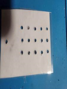
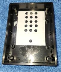
The PC boards were delivered on Tuesday, September 2nd, after which assembly and testing commenced. On Wednesday, September 3rd, all components were installed into the enclosure. The silk screen area on the PC board was printed, laminated, and then perforated with a hole punch to create a template.
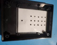
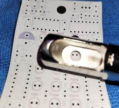
For another project box drilled yesterday, an alternative method was used. A template was produced in the same manner; however, rather than laminating it, a glue stick was utilized to adhere the paper template directly to the interior of the enclosure. This procedure required a longer hole punch. To accurately position the holes, the cover was opened to empty the hole punch and align the locations as needed.
A drill press attachment for a Dremel drill was used to make starter holes in the template, and a cordless hand drill enlarged the holes due to a lack of suitable Dremel drill bits for the LEDs and push button. Since the PC board size allows, the switch is mounted through holes in both the board and the top of the case, securing the board to the enclosure.
This project is available as a shared project. The Gerber files and KiCad project can be accessed here:
https://www.pcbway.com/project/shareproject/W896177ASV12_SlotMachine_kicad_pcb_21ffcde7.html
All individuals are welcome to utilize any of my projects as a foundation for their own work, which may also be shared. While it is not obligatory, including a link to my original project in your documentation would be appreciated. If you build one of my designs and develop a custom 3D case, you are encouraged to share it; I would be pleased to add a link to the description.
Please note that these projects have been developed for hobbyist purposes and have not been designed with manufacturing considerations in mind. Creating production-ready boards would require further PCB design efforts. However, if you wish to adapt any of my projects for commercial or personal development, you are welcome to do so.