1. Blog>
  2. How to Use Breadboards for Your Projects

How to Use Breadboards for Your Projects

by: Sep 05,2025 1723 Views 0 Comments Posted in PCB Basic Information

Electronics Breadboard DIY Learn Tutorial

Summary:       This blog explains how to use breadboards for electronics projects. It covers what breadboards are, what they’re used for, and how to get started by choosing the right size and preparing tools. It shows how breadboards work with power rails and columns, how to turn schematics into real builds, and how to power, test, and debug safely.

1. Introduction

What is a Breadboard?

  • A breadboard is a reusable prototyping board that allows you to connect electronic components without soldering, It consists of rows and columns of conductive strips hidden under the plastic surface, where components and jumper wires can be easily inserted.
  • Breadboards are especially popular with beginners and hobbyists because they make it easy to test, modify, and debug circuits before committing to a permanent PCB design.


2. What Can Breadboards Be Used For?

Breadboards are widely used in electronics for:

  • Prototyping new circuits – test designs before soldering them onto a PCB.
  • Learning and teaching – ideal for students to understand circuit connections.
  • Quick experiments – try different configurations without wasting materials.
  • Debugging – identify component failures or circuit issues quickly.


3. How to Get Started

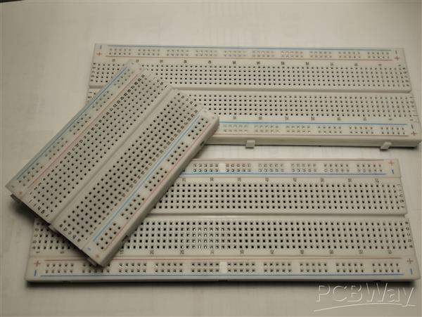
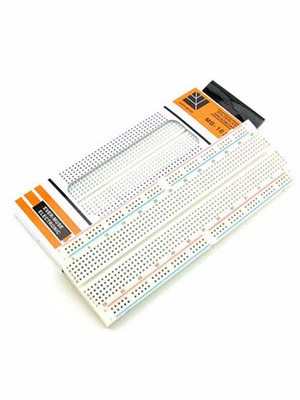
Choose the Correct Size and Type

Breadboards come in various sizes:

  • Mini breadboards – small, portable, good for single ICs or simple circuits.
  • Half-size breadboards – balance of space and portability, great for hobbyists.
  • Full-size breadboards – lots of space, suitable for larger circuits or classroom use.
  • Some breadboards also include built-in power rails or come pre-mounted on project kits with extra features.


(Photo showing different sizes of a breadboard)


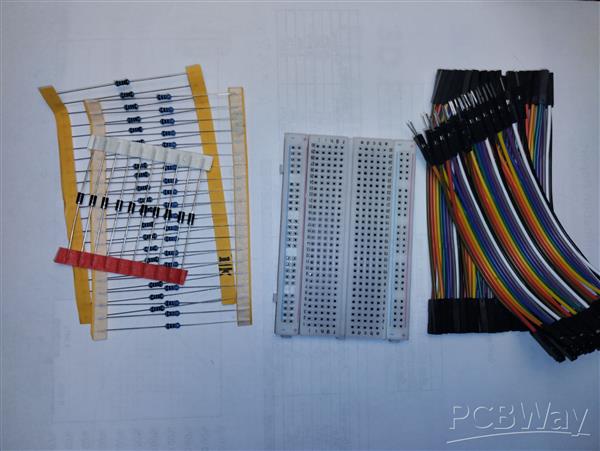
Prepare Everything You Need

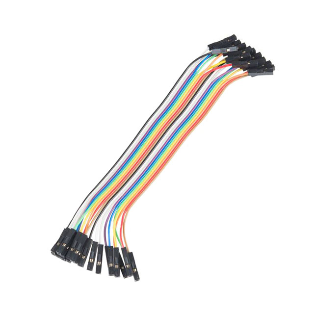
Before you begin, gather:

  • Breadboard(s) of the right size
  • Jumper wires (male-to-male for breadboards, female-to-male for modules)
  • Electronic components (resistors, capacitors, LEDs, ICs, etc.)
  • A power source (5V or 3.3V regulated supply, or a USB module)


4. How Does a Breadboard Work and How to Use It

A breadboard has an internal layout that connects holes in a specific way:

  • Power rails – the long strips running down the sides, usually marked red (+) and blue (–). These provide power to your components.
  • Terminal strips – the central area where components are placed. Each column of 5 holes is connected internally.
  • Gap in the middle – separates the two sides of the board, allowing ICs to sit across the gap so each pin connects to a different row.

(Down below, we can see how the Breadboard works)
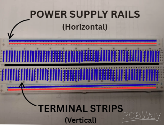

To use it:

Connect your power supply to the rails.

Place components in the terminal strips.

Use jumper wires to connect parts of your circuit.

This system makes circuits quick to assemble and modify.


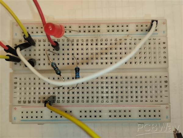
5. Turn Your Schematics into Breadboard Projects

Once you’ve drawn your circuit schematic, you can translate it into a breadboard layout:

  • Identify power connections first and connect them to the rails.
  • Place ICs and modules across the central gap.
  • Add supporting components (resistors, capacitors, LEDs) around the IC.
  • Use jumper wires to make the connections according to the schematic.


This step teaches you how to move from theory (schematic) to practical build (breadboard).


6. Power On, Testing, and Debugging

Power On: Carefully connect your power supply (always start with the lowest safe voltage).

Testing: Check each part of the circuit step by step instead of all at once. For example, test if the LED lights up before connecting more parts.

Debugging: If it doesn’t work, double-check:

  • Are components placed in the right rows?
  • Are jumper wires in the correct spots?
  • Are the power rails properly connected?

Using a multimeter is highly recommended for troubleshooting.


7. Warnings and General Information

Breadboards are incredibly useful, but they have limitations:

Voltage: Most breadboards are safe up to tens of volts. Going higher can cause arcing or melting.

Current: Individual rows can usually handle ~1A max, but continuous high current can heat or deform contacts.

Contact reliability: Over time, the spring contacts may loosen, causing poor connections.

Not permanent: Breadboards are only for testing — for long-term use, design a PCB.


Always check your power requirements and use breadboards within safe operating limits.

Tools, APP Software Used etc.
Google Sheets
Schematic and Layout
Join us
Wanna be a dedicated PCBWay writer? We definately look forward to having you with us.
  • Comments(0)
Upload photo
You can only upload 5 files in total. Each file cannot exceed 2MB. Supports JPG, JPEG, GIF, PNG, BMP
0 / 10000
    Back to top