DRC (Design Rule Check) is an essential step in PCB Layout design that ensures your layout complies with the manufacturing capabilities of the PCB fabrication house. Performing DRC before sending your PCB Layout for production is critical to guarantee design reliability and to avoid issues such as shorts, opens, or assembly failures. Without proper DRC checks, even a well-planned PCB Layout may face serious reliability risks in real-world applications.
Every manufacturer has its own process limitations, and DRC uses EDA tools (such as Altium Designer, Cadence Allegro, or KiCad) to automatically validate whether a PCB Layout violates those constraints. You can find the PCBWay’s DRC guidelines here.
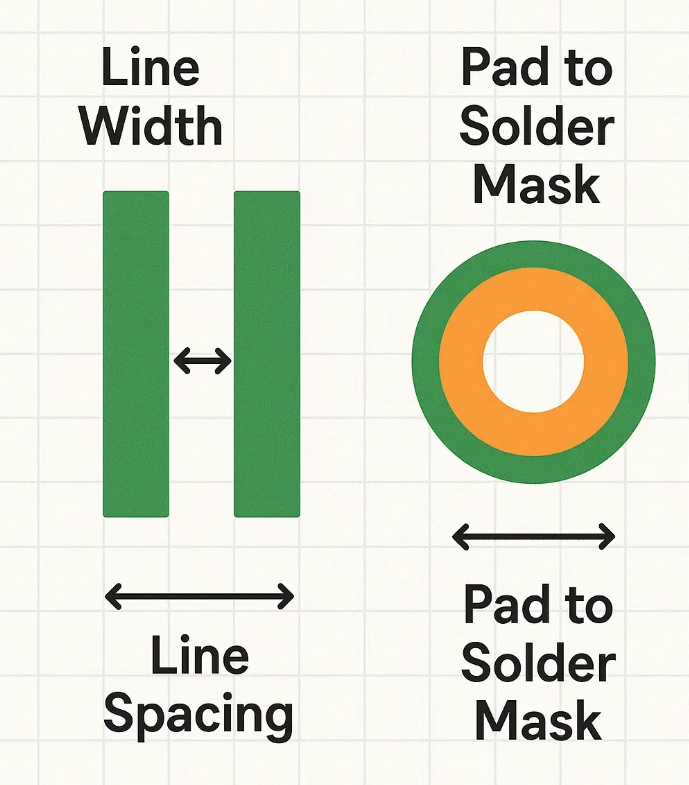
DRC focuses on physical clearances and design dimensions that directly affect PCB Layout reliability, including:
DRC is more than just a final checklist, it is a core tool that fundamentally enhances PCB Layout reliability. By applying automated and precise rule verification, DRC eliminates potential design flaws at the layout stage, preventing them from turning into costly errors in the finished PCB.
A PCB Layout that cannot be fabricated is automatically unreliable. DRC ensures manufacturability by aligning your design with the PCB factory’s capabilities—minimum drill sizes, trace widths, and spacing. This guarantees that the design can be built consistently and that reliability is maintained in mass production.
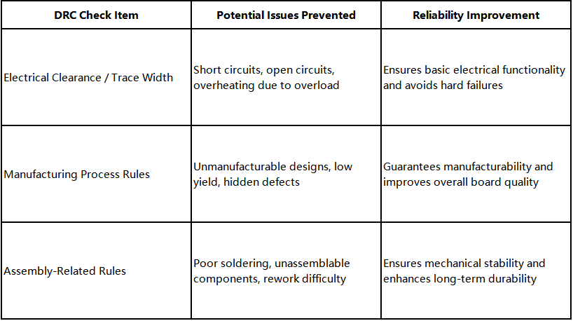
By applying DRC systematically, designers can ensure that their PCB Layout complies with electrical, manufacturing, and assembly requirements. This prevents shorts, opens, and fabrication errors, while also improving soldering and assembly reliability. Ultimately, DRC transforms a PCB Layout into a reliable product design, ready for successful manufacturing and long-term performance.
Feel free to contact PCBWay if you have any more question.


